Since we now have a beautiful robotic chassis, we’re ready to continue our Building A Robot series, and get serious with some motor control. This second part of building a robot is perhaps the most crucial as it will define what type of control we will have over the motors. Ideally, we want a simple method for controlling the motors so that our software is free to do other things.
In this article we will move forward with the Building A Robot series by adding the electronics necessary to control the speed and direction of both motors on the robotic chassis, which we developed in the previous article, Part 1: The Chassis. The two main additions in this portion of the project are a microcontroller and a motor controller IC.

Purpose & Overview of this tutorial
The goal of this part of the project is to build up firmware for a microcontroller that can tell a motor controller IC to move the motors at specific speeds and directions. To verify that we have good control over the system, our core goal for this part is to make the robot be able to move forward, turn around and then continue back, then turn around and move forward…over and over. If we can build a program for the microcontroller that makes the robotics platform do that, our goal will be reached for this part.
The microcontroller that we will use for this part of the Building A Robot series is the PIC 18F252 8-bit microcontroller. It is manufactured by microchip, and most of my tutorials/projects on this website use the PIC. The motor controller IC that we will use is the same as some other tutorials, the SN754410NE Quadruple Half-H Driver.
SN754410 Motor Controller
PICkit Programmer
7x 10kΩ Resistors
2x 2N2222 Transistors
2x 10 uF Capacitor
2x 100 uF Capacitor
40 MHz Crystal
Jumper Wire
10mm Green LED
10mm Yellow LED
10mm Red LED
Robotics Chassis (Part 1)
Parts List Details
All the parts used in this part ofBuilding A Robot are listed above and you can see a more detailed description of the main parts below, in case you’ve never heard of them before or you’re not sure what their ‘role’ is in the circuit we’re going to create.
PIC 18F252
This is a microcontroller which is basically a CPU + Program Memory. That means we can load a program onto it, and just like a computer it will run the program’s instructions. We’ll be using this 28 pin PIC to tell the motor controller what to do and to control some output LEDs.
PICkit Programmer
Every microcontroller requires a programmer in order for you to load your compiled program onto it. The PICKit is solid programmer, version 2 and version 3 are both excellent choices.
SN754410 Motor Control IC
The motor controller that we’ll be using is the SN754410NE. It’s a ‘Quadruple Half H-bridge’. What this means is that it can control two DC motors, or one Stepper motor. This is a cheap and reliable IC that fits nicely onto the breadboard we’re using.
40 MHz Crystal
The microcontroller that we’re using doesn’t have an internal oscillator, so we’ll add a simple two pin crystal that has 40 MHz. The PIC actually requires 4 crystal periods for every instruction execution, so the real ‘clock speed’ for our microcontroller will be 10 MHz.
2N2222 Transistors
Two of these generic transistors will be used to assist the PIC in sending the proper signals to the motor controller. The motor controller requires differential PWM input and these transistors will be used to create that second (differential) input for each motor.
Jumper Wires & LEDs
Since we’re using a basic tiny breadboard we will use all jumper wire to connect the parts together. This offers us maximum flexibility while not taking away too much efficiency. A few ‘debug’ LEDs will be added to help us see what ‘state’ the robotics platform is in while it is driving.
Schematic Overview
The schematic for controlling the motors is split up into three main parts, with each part having a unique functionality. The main parts used and seen in the schematic below are the 18F252, SN754410 and 2N2222 Transistors.
Schematic Specifics
Microcontroller Circuit
Seen at the very top, the microcontroller circuit consists of the PIC 18F252, its 40 MHz crystal, a few LEDs, the enable lines going to the motor controller and the PWM signals going to the PWM inversion circuit and the motor controller.
PWM Inversion Circuit
Two transistors (2n2222) are used to invert the two PWM signals that are travelling to the motor controller. This is done because the motor controller needs to have both the ‘positive’ PWM signal and the ‘negative’ PWM signal in what is called a differential pair. The motor controller cannot control our DC motors without both the positive and negative PWM signals.
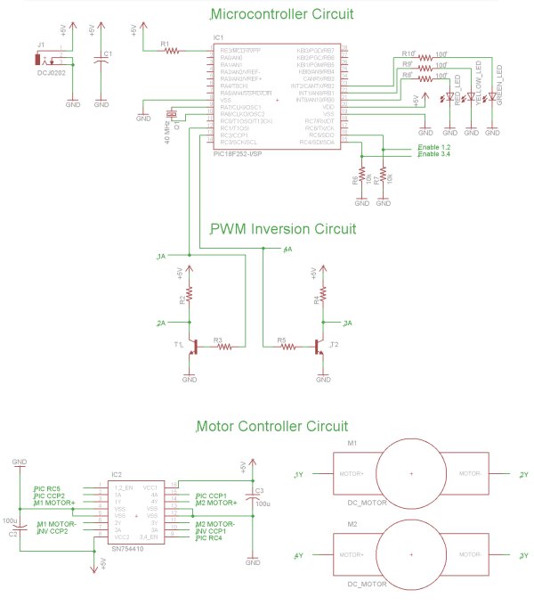
Motor Control Circuit
The main part used for the motor control circuit is the SN754410. This is a quadrule half h-bridge motor controller IC. To use this motor controller, you must input a differential PWM signal, provide power and ground and enable the bank to start-up your motors. The control signals that will tell the motor controller to do all this will be sent from the PIC.
The Theory
The theory for how this motor control system works will be described in two parts. The first part describes the input signal called PWM short for Pulse with Modulation and the second will describe which pulses go where to control speed and direction.
The two images above show you two different PWM signals. The first signal is “on” 80% of the time. That means it is at +5v for 80% of the period of the signal. This is a powerful signal and if input into the SN754410, would make a motor spin very fast — forward. The second image shows you a signal similar to the first, but it is only on 30% of the time. It is at +0v for 70% of the period of the signal. Since this PWM signal is in an ‘off’ state for the majority of the time, this will actually make the SN754410 tell the motor to spin in reverse at a medium speed. The center point, 50%/50% tells the motors to stay idle with no movement.
Looking at one side of the SN754410, we have a motor connected to 1Y and 2Y. A PWM signal that is 80% on // 20% off is input into 1A and the differential signal to 2A. The corresponding output to the motor makes it turn very fast (almost full speed) in the clockwise direction.
If we look at the same setup but change the input PWM to 20% on // 80% off , the motor will spin counter-clockwise (reverse) rather at roughly the same speed as the previous example. The motor spins in the opposite direction because the current is being input on the other side of the motor (pin 2A), thusly it flows the opposite direction through the motor compared to the first example.
Hardware Design
For this part of the project we will assemble the circuit seen in the schematic to the robot chassis from Part 1: The Chassis. The circuit assembly is a step by step process that I took photos of so that you could easily follow along. So let’s get started!
Building The Circuit
· Below you can see all of the parts used in this circuit laid out on a table.
All the power supply connections to the breadboard are made.
The basic PIC 18F252 circuit is assembled.
The motor controller circuit is assembled at the other end of the breadboard.
The PWM Inversion circuit is built to connect the PIC to Motor Controller.
The last step is connecting the 3 Output LEDs to the breadboard.
·The circuit is complete, now we need to program the PIC with firmware.
The Software
There are two main portions of code that we are concerned with:
-The Initializations
-Motor Control Steps
The first part of the firmware program that we’ll look at is the initializations. These configure the PIC’s outputs and setup the PWM hardware module. PORTB and PORTC will be used as outputs, so TRISC and TRISB are cleared. Timer2 is used with the hardware PWM module, so we need to set it’s pre-scalar value. Finally, the PWM modules are opened up and set to about 7.5 KHz.
For more detail: Building A Robot: Motor Control
About The Author
Ibrar Ayyub
I am an experienced technical writer holding a Master's degree in computer science from BZU Multan, Pakistan University. With a background spanning various industries, particularly in home automation and engineering, I have honed my skills in crafting clear and concise content. Proficient in leveraging infographics and diagrams, I strive to simplify complex concepts for readers. My strength lies in thorough research and presenting information in a structured and logical format.
Follow Us:LinkedinTwitter