
A Message from me: Hello! Thank you for reading my first instructables on building a pulse analyzer using PIC24f in Assembly language. I have almost completed the project, but not yet finished writing this instructables as I want it to be as comprehensive as possible. It will take me another week to finish writing. Please comment or inbox me if you have any questions! 🙂
#############################################################################################
Record pulse amplitude is not a difficult thing to do; however, if the pulse is super short — by that I mean, on the scale of hundreds of nano seconds, we cannot use an Arduino anymore, as each command in a higher level language always takes too long to execute. Thus, before the amplitude is recorded, the pulse is already gone!
To solve this problem, we are going to abandon all the higher-level, easy-to-use languages and actually write a program to a microcontroller in Assembly language, as in a low level language environment runs so much faster, which is what we want.
=================================================================================
Hardware we need:
– Microchip PICkit2 (used for to write the program into the microcontroller)
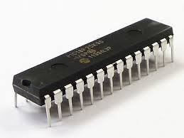
– Microchip PIC24F04KA200 (PIC24 16-bit Microcontroller)
– Analog Devices AD781JN Sample and Hold (essential to make the measurement)
– Electronic stuff (breadboard, wire, battery, capacitors, resistors…)
– Osciloscope
– Function Generator
– UART wire with tx, rx, gd lines to connect the microchip to your computer
=================================================================================
Software we need:
– MPLAB IDE v8.30
-MATLAB
===================================================================================
Documents attached:
AD781.pdf: about SAMPLE & HOLD
PIC24f.pdf: about PIC24f microcontroller
PIC30F Programmers Reference Manual.pdf: Assemly instructions
PIC24f Assembler: Explanation on how to write in Assembly
Attachments
- AD781.pdfDownload
- PIC24f Assembler.pdfDownload
- PIC24f.pdfDownload
- PIC30F Programmers Reference Manual.pdfDownload
Step 1: Writing in Assembly for Dummies
Open MPLAB IDE and create a new source file “*.s” so that your file will be in assembly mode and the correct colors will show up. For example instructions are in blue, comments are in green and names are in red.
There are some basic but essential instructions in Assembly that we are going to need to use for our project. Along the lines of explaining each instruction, I will also talk about some have-to-know and fundamental things about the machine logics (for example that a logic HIGH/”1″ is an input, and a logic LOW/”0″ is an output). So, don’t miss out anything while reading! These instructions are very easy to comprehend as the purpose of Assembly is to be able to communicate with machine. And machines, different from human brain, cannot accept very complicated logics. We have to break done the complicated problem to numerous simple steps to be able to write in Assembly. In this way, we can say that Assembly is both easy (every single step) and complicate (in general once the program gets super long)! Try not to lose the BIG PICTURE while writing in Assembly!
Here are some introduction for some basic instructions:
===================================================================================
MOV:
MOV instruction takes in 2 parameters and move the first parameter value into the second parameter. In general, we use #lit8 or #16 to express a literal number; Wns (start) and Wnd (destination) are used to express a selected working register.
Example: if we want to move a number (let’s say 8), into a working registor, then we simply write:
MOV #8, W0
===================================================================================
BSET:
BSET instructions will set a particular bit of a particular register to be HIGH, which is 1. It takes in two parameters: first one is the name of the register; second one is the number of the bit within that particular register you have selected in the first parameter.
Example: if we want to set PORTB, bit 1 to be an input pin, then we write:
BSET PORTB, #1
==================================================================================
BCLR:
BCLR instructions will set a particular bit of a particular register to be LOW, which is 0. It takes in two parameters: first one is the name of the register; second one is the number of the bit within that particular register you have selected in the first parameter.
Example: if we want to set PORTA, bit 0 to be an input pin, then we write:
BCLR PORTA, #0
==================================================================================
BTSS:
BTSS means “bit test skip if set”, which again takes into two parameters of a register and a bit. This intruction will test on the particular bit; if this bit is HIGH, then the next line is skipped. This is very useful in using loops.
==================================================================================
BTSC:
BTSS means “bit test skip if clear”, which again takes into two parameters of a register and a bit. This intruction will test on the particular bit; if this bit is LOW, then the next line is skipped. It comes in a pair with BTSS.
=================================================================================
BRA:
BRA means “branch” which takes in one parameter: the name of the set of instructions you have names before. This goes well with the BTSS and BTSC instruction. For example:
Loop: BTSS PORTA, #0
BRA Loop
The above lines are telling us: if PORTA #0 is high, then it will skip the line “BRA Loop” to get out of the loop; if it is low, then it goes back to the Loop instruction and keep doing the BTSS instruction. It is important to notice that only put letters when naming your instruciton loops, dont name thins like “IsItDone?”, Assembly does not like this kind of names…
================================================================================
NOP:
This just means no operation, which is useful when you just want the program to wait for a particular length of time.
Step 2: Generate an Output Signal Whenever Encounter a Pulse
So now let’s start building the pulse analyzer. Since we want to use Sample and Hold to record the pulse amplitude, we need to switch on the S/H whenever there is a pulse. So the first step is to write a program that tells PIC24F to send out a pulse (as the switch to S/H) whenever there is a pulse for which we want to measure its amplitude.
====================================================================================
; select the p24FJ32GA002 processor
.equ __p24FJ32GA002, 1
; include the processor definitions
.include “p24FJ32GA002.inc”
;Configuration bits ;
config __CONFIG1 0x3f7f
config __CONFIG2 0x79cf
.global __reset ;The label for the first line of code.
;……………………………………………………………………
; Code Section in Program Memory ; (THIS IS WHERE THE PROGRAM WILL START AFTER RESET) ;…………………………………………………………………… ;
.text ;Start of Code section
__reset:
;RB1 pin5; RB2 pin6; RB3 pin7; RA0 pin2.
BCLR TRISB, #1
BSET TRISA, #0
BSET AD1PCFG, #0 ; set the pin to be digital input
;LOOP1&2 CHECKS IS IT IS A RISING EDGE
LOOP:
LOOP1: BTSS PORTA, #0 ;SKIP IF LEVEL IS HIGH
BRA LOOP1
BSET LATB, #1 ;GIVES AN OUTPUT SIGNAL
BCLR LATB, #1
LOOP2: BTSC PORTA, #0
BRA LOOP2 ;SKIP IF LEVEL IS LOW
BRA LOOP
.end ;End of program code in this file
==================================================================================
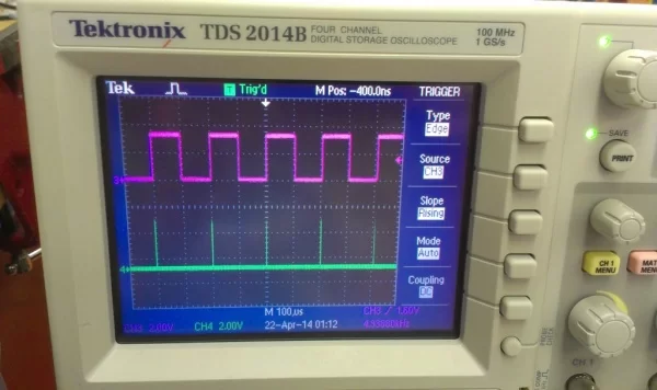
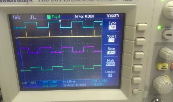
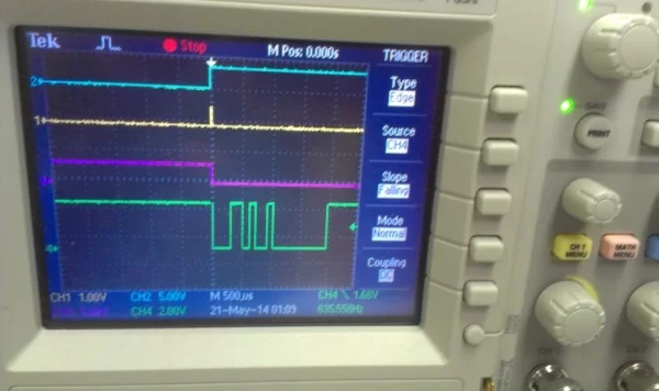
Above is a picture of the oscilloscope screen. The pink chanel is the input to microchip. Whenever there is a rising edge, then it generates a short pulse and the oscilloscope will record it. That is the green peaks we are seeing. The width of each generated pulse is about 250ns, which is pretty fast!! YAY 😀
Step 3: Connecting With the S/H
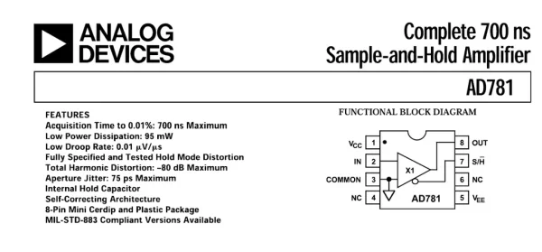
Start from reading the pin diagram for sample and hold. The short pulse of which we want to measure the amplitude should be going into Pin 2 of S/H. Once there is a pulse going in, we want to turn on the switch for S/H, which is Pin 7. Once Pin 7 is set low, then it starts to hold which means the capacitor start to charge to the amplitude of the pulse we want to measure. The outpuse pulse comes out from Pin 8 which has the same amplitude of the input pulse.
As a start, we can use a function generator to give a pulse. Use SYNC as the switch signal to microchip. OUTPUT from the function generator should connect to Pin 2 of S/H. Once the microchip receives the SYNC as high, then it outputs a low signal to S/H to turn on the hold mode. And connect an oscilloscope to pin 8 of S/H to see if the amplitude increases or not when the function geenrator pulse increases.
Step 4: Analogue Digital Converter
To be able to record all the data, we want our microchip to read the output signal from S/H as an analogue signal and record it and use a USB serial Port to transfer to MATLAB program.
To set up an a/d conversion on PIC24F (the following steps are taken from page 87 of “PIC24f.pdf”):
Configure the A/D module:
a) Select port pins as analog inputs(AD1PCFG<15:0>).
b) Select voltage reference source to match expected range on analog inputs (AD1CON2<15:13>).
c) Select the analog conversion clock to match desired data rate with processor clock (AD1CON3<7:0>).
d) Select the appropriate sample/conversion sequence (AD1CON1<7:5> and AD1CON3<12:8>).
e) Select how conversion results are presented in the buffer (AD1CON1<9:8>).
f) Select interrupt rate (AD1CON2<5:2>).
g) Turn on A/D module (AD1CON1<15>).
Step 5: Code With Comments for Pulse Analyzer (Some Notes on the Next Section!)
; select the p24FJ32GA002 processor
.equ __p24FJ32GA002, 1
; include the processor definitions
.include “p24FJ32GA002.inc”
;……………………………………………………………………
;Configuration bits ;……………………………………………………………………
config __CONFIG1 0x3f7f
config __CONFIG2 0x79cf
; Equating registers into names that are easy to use.
.equ ad1con1, 0x320 ; basic ad control register
.equ ad1con3, 0x324 ; ad control register for setting conversion clock speed
.equ ad1buf0, 0x300 ; ad results end up here
.equ ad1chs0, 0x0328 ; ad channel select register
.equ ad1pcfg, 0x32c ; this register isused to configure inputs for analog or digital
.global __reset ;The label for the first line of code. ;
……………………………………………………………………
; Code Section in Program Memory ; (THIS IS WHERE THE PROGRAM WILL START AFTER RESET) ;…………………………………………………………………… ;
.text ;Start of Code section
__reset:
;;;;;;;;;;;;;;;;;;;;;;;;;;;;;;;;;;;;;;;;;;;;;;;;;;;;;;;; ;pin connection;;;;;;;;;;;;;;;;;;;;;;;;;;;;;;;;;;;
;Output: RB4 pin11; Input: RA0 pin2
;UART: rx: pin6; tx: pin7
;AN9: pin26 S/H outputs to this pin (this pin is an input for microcontroller)
;;;;;;;;;;;;;;;;;;;;;;;;;;;;;;;;;;;;;;;;;;;;;;;;;;;;;;;;;;;;;;;;;;;;;;;;;;;;;;;;;;;;;;;;;;;;;;;;;;;;;;;;;;;;;;;;;;;;;
;Connectin with UART2: Translate the code from serialcomm.pb for logochip
;write $02c8 $f0a4
MOV #0xf0a4, W0
MOV W0, TRISB
;write $6c2 $0500
MOV #0x0500, W0
MOV W0, RPOR1
;write $6a6 $1f02
MOV #0x1f02, W0
MOV W0, RPINR19
;write $238 51 ; setting baud rate
MOV #51, W0
MOV W0, U2BRG
;write $230 $8800
MOV #0x8800, W0
MOV W0, U2MODE
;write $232 $400
MOV #0x400, W0
MOV W0, U2STA
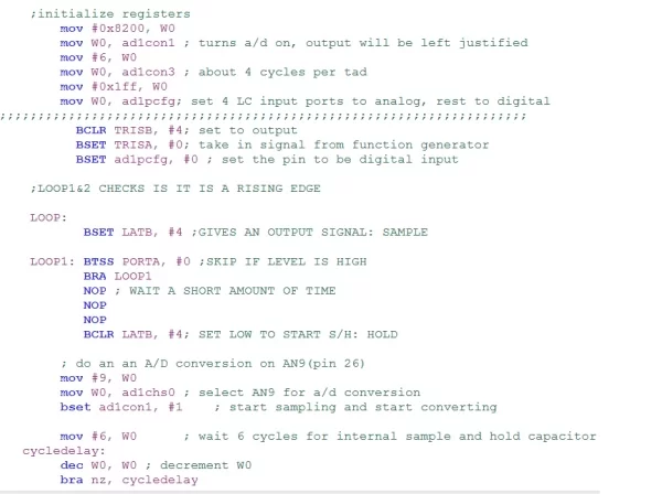
;initialize registers
mov #0x8200, W0
mov W0, ad1con1 ; turns a/d on, output will be left justified
mov #6, W0
mov W0, ad1con3 ; about 4 cycles per tad
mov #0x1ff, W0
mov W0, ad1pcfg; set 4 LC input ports to analog, rest to digital
;;;;;;;;;;;;;;;;;;;;;;;;;;;;;;;;;;;;;;;;;;;;;;;;;;;;;;;;;;;;;;;;;;;;;
BCLR TRISB, #4; set to output
BSET TRISA, #0; take in signal from function generator
BSET ad1pcfg, #0 ; set the pin to be digital input
;LOOP1&2 CHECKS IS IT IS A RISING EDGE LOOP:
BSET LATB, #4 ;GIVES AN OUTPUT SIGNAL: SAMPLE
LOOP1: BTSS PORTA, #0 ;SKIP IF LEVEL IS HIGH
BRA LOOP1
NOP ; WAIT A SHORT AMOUNT OF TIME
NOP
BCLR LATB, #4; SET LOW TO START S/H: HOLD
; do an an A/D conversion on AN9(pin 26)
mov #9, W0
mov W0, ad1chs0 ; select AN9 for a/d conversion
bset ad1con1, #1 ; start sampling and start converting
mov #7, W0 ; wait 7 cycles for internal sample and hold capacitor to charge
cycledelay: dec W0, W0 ; decrement W0
bra nz, cycledelay ; now wait for conversion to finish
bclr ad1con1, #1 ; start holding
done: btss ad1con1, #0 ;
bra done ; wait for conversion to be done
; left justified results are contained in ad1buf0
mov ad1buf0, W0
lsr W0, #8, W0 ; move copy of ad1buf0, shifted 8 bits to the right, to W0
mov W0, U2TXREG ; write these 8 high bits to tx ; wait for transmission to finish
txdone: btss U2STA, #8;
bra txdone
mov #0x0c0, W0 ; mask to select bits 6 and 7
and #0x300, W0 ; and puts copy of bits 6 and 7 in W0, all other bits are zero
mov W0, U2TXREG; write these bits to tx, remember to process correctly in MATLAB
LOOP2: BTSC PORTA, #0
BRA LOOP2 ;SKIP IF LEVEL IS LOW
BRA LOOP
Step 6: Notes and Unsolved Mysteries on the Code
1. Cycle delay
Notice that there is a “cycle delay” loop which is used for to wait the internal sample and hold for the microchip to charge. Here we set it to be 7 cycles; interestingly, it will not work at all if we change to 6 cycles or any number smaller than 6. This is quite strange and mysterious. If 6 cycles are not enough for the microchip’s S/H to charge, than we should instead get some other smaller number, however, what happened instead is that if we use 6 cycles, nothing goes through and we will be stuck in the “done” loop as if the a/d conversion is never done.
2. Data transmission
Since we are transferring a 10 bit data into our MATLAB, but the UART2 only takes in 8 bits per time. So we will transfer the first eight bits first and then transfer the last two digits. Thus, in the MATLAB program, we need combine every two digits into a desired answer. The basic calculation for that is just: (1st-byte * 4 + 2nd-byte / 64) as we want the high byte to move forward(left) by two digits and the low byte to move to right by 64 (2^6).
Step 7: Use MATLAB & USB Serial Board to Read the Data
A super crude way to draw the data points in real time has the following code:
==================================================================================
clf
delete(instrfindall) % remove all traces of any prior connections
s= serial(‘COM8’); % create serial port object
% You’ll need to check Windows device manager for correct port #!!
%set(s,’BaudRate’,19200); % this is how you set the baud rate
% The fopen command is needed to explicitly establish the
% connection between MATLAB and the USB-serial board
fopen(s) hold on
for i=1:500
a = fread(s,2);
sensorvalue = a(1)*4 + a(2) / 64; plot(i,sensorvalue,’c*’)
S(i) = sensorvalue;
drawnow
end
hist(S) % draw a histogram
hold off
fclose(s) delete(s) clear s
===================================================================================
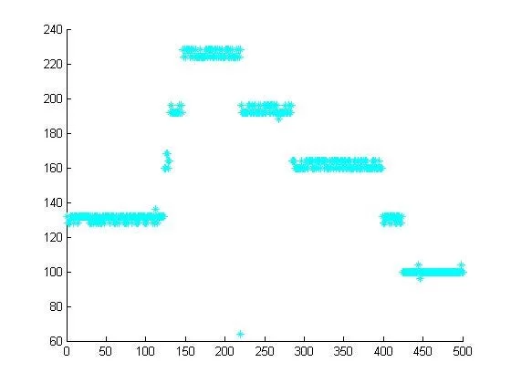
Above is a picture of MATLAB drawing the data points in real time and I am changing the amplitude of the input pulse from a function generator. We see that the data points clearly shows the amplitude of the short pulses! Also, I added a histogram
SUCCESS!!!
However, notice that I have commented out the line to set the Baud rate to be 19200. Currently the Baud rate is only 51, we can increase it but not to 19200 as we can’t really observe the change anymore as the program is reading the data way too fast.
Step 8: Playing Around With the Pulse Analyzer
We found that the shortest pulse possible to be analyzed is 7 micro seconds! but not 6!
We don’t even need an external sample and hold as the microchip’s internal sample and hold can actually do all the work. But at least we get to really understand and see how sample and hold works through all the work we have done!
Please leave comments if you have any question and things you want to say!
Special thanks to Professor Berg at Wellesley College Department of Physics to be my adviser!! It’s been a fun project!!!
Source: Build a Pulse Analyzer
About The Author
Muhammad Bilal
I am a highly skilled and motivated individual with a Master's degree in Computer Science. I have extensive experience in technical writing and a deep understanding of SEO practices.