
A BlinkLED is a LED that has its own PIC microcontroller. Blink patterns and blink rates are programmable and BlinkLEDs can be used individually (for LED Throwies) or in strings for holiday or special lighting.
I made these because I wanted to trim my Christmas tree with individual blinking lights. With the BlinkLED, I can do that easily and safely. The BlinkLED daisy chains with 2 thin nearly invisible wires (#30 AWG wire wrap wire) and runs from a 3 – 5 volt dc power supply or battery so no high voltage (120 vac) wiring is required. 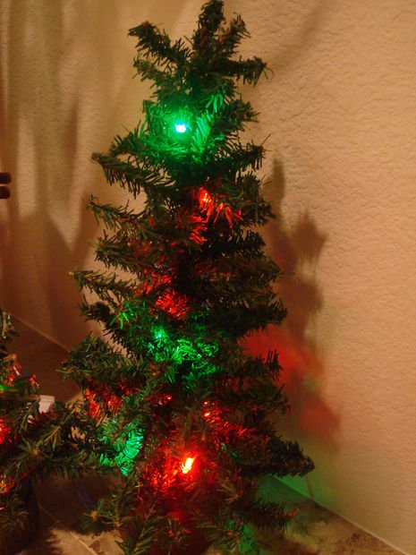 The video shows BlinkLEDs that blink and change color alternating between red and green. The time each BlinkLED remains in one color is randomly determined.
So that there are no surprises later, you will have to have electronic assembly skills and equipment to program PIC microcontrollers.
Step 1: Choose the components
For each BlinkLED, you will need the following:
1 ea Microchip 12F509 PIC Microcontroller (Mouser PN 579-PIC12F509-I/P)
1 ea 22 ohm, 1/4 watt resistor (Mouser PN 291-22-RC). I used a 22 ohm resistor in my prototype but any value between 22 and 220 ohms will work. It depends on the supply voltage you will be using, the voltage drop across the LED, and the forward voltage of the LED. You want to choose a value that will result in a current of 10 to 20 milliamps through the LED. As a rule of thumb, resistor value in ohms equals the supply voltage minus .5 volts minus the voltage drop of the LED divided by the LED current in amperes (1 milliampere = .001 ampere). For example, for a green LED which typically has a 2.2 voltage drop with a 3.2 volt power supply: R = (3.2 volts -.5 volts -2.2 volts) / .020 amps = 25 ohms.
Keep in mind that different colored LED have different voltage drops across them when lite. Typical values are: Green 2.2 volts, Yellow 2.1 volts, Red 2.0 volts, Blue 3.8 volts, and White 3.2 volts. You will have to increase the supply voltage when using Blue and/or White LEDs in order to drive them to full brightness.
1 ea LED. Just about any LED will work. For my prototype, I chose a green LED removed from a Christmas light string. These have a wide viewing angle because of the flat concave top.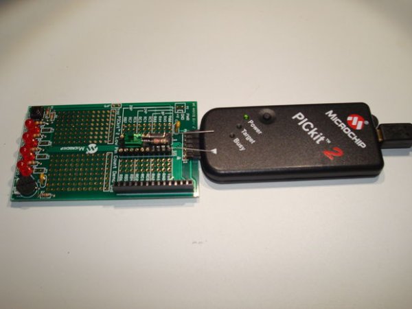
Step 2: Assemble your BlinkLED
About The Author
Ibrar Ayyub
I am an experienced technical writer holding a Master's degree in computer science from BZU Multan, Pakistan University. With a background spanning various industries, particularly in home automation and engineering, I have honed my skills in crafting clear and concise content. Proficient in leveraging infographics and diagrams, I strive to simplify complex concepts for readers. My strength lies in thorough research and presenting information in a structured and logical format.
Follow Us:LinkedinTwitter