
When you connect a microcontroller to a sensor, display, or other module, do you ever think about how the two devices talk to each other? What exactly are they saying? How are they able to understand each other?
Communication between electronics is like communication between humans. Both sides need to speak the same language. In electronics, these languages are called communication protocols. Luckily for us, there are only a few communication protocols we need to know when building most DIY electronics projects. In this series of articles, we will discuss the basics of the three most common protocols: Serial Peripheral Interface (SPI), Inter-Integrated Circuit (I2C), and Universal Asynchronous Receiver/Transmitter (UART) driven communication.
First, we’ll begin with some basic concepts about electronic communication, then explain in detail how SPI works. In the next article, we’ll discuss UART driven communication, and in the third article, we’ll dive into I2C.
SPI, I2C, and UART are quite a bit slower than protocols like USB, ethernet, Bluetooth, and WiFi, but they are a lot more simple and use less hardware and system resources. SPI, I2C, and UART are ideal for communication between microcontrollers and between microcontrollers and sensors where large amounts of high speed data don’t need to be transferred.
SPI is a common communication protocol used by many different modules. For example, SD card modules, RFID card reader modules, and 2.4 GHz wireless transmitter/receivers all use SPI to communicate with the microcontroller.
One unique benefit of SPI is the fact that data can be transferred without interruption. Any number of bits can be sent or received in a continuous stream. With I2C and UART, data is sent in packets, limited to a specific number of bits. Start and stop conditions define the beginning and end of each packet, so the data is interrupted during transmission.
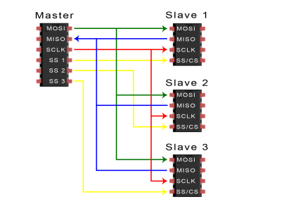
Devices communicating via SPI are in a master-slave relationship. The master is the controlling device (usually a microcontroller), while the slave (usually a sensor, display, or memory chip) takes instruction from the master. The simplest configuration of SPI is a single master, single slave system, but one master can control more than one slave (more on this below).
For More Details: Basics of the SPI Communication Protocol
About The Author
Ibrar Ayyub
I am an experienced technical writer holding a Master's degree in computer science from BZU Multan, Pakistan University. With a background spanning various industries, particularly in home automation and engineering, I have honed my skills in crafting clear and concise content. Proficient in leveraging infographics and diagrams, I strive to simplify complex concepts for readers. My strength lies in thorough research and presenting information in a structured and logical format.
Follow Us:LinkedinTwitter