BA1404 HI-FI Stereo FM Transmitter 88 – 108 MHz usnig pic microcontoller

BA1404 Stereo FM Transmitter Components:
BA1404 IC
38KHz Crystal
L1 – 3.5 Turns Variable Coil
1x PCB
1x 38KHz Crystal Oscillator
1x DIP-18 IC Socket
1x 3.5T Variable Precision RF Coil
1x 10uH Inductor
4x 10uF/50V Gold Audio Capacitors
4x 1nF Ceramic Capacitors
2x 1nF Mylar Capacitors
1x 220pF Ceramic Capacitor
5x 10pF Ceramic Capacitors
2x 47K 1% Metal Film Resistors
2x 27K 1% Metal Film Resistors
1x 150K 1% Metal Film Resistor
1x 5.6K 1% Metal Film Resistor
1x 270 1% Metal Film Resistor
  Technical Specifications:
Supply Voltage: 1.5 – 3V
Dimensions: 49 mm x 32 mm x 10 mm (W x H x D)
 BA1404 HI-FI Stereo FM Transmitter 88 - 108 MHz
BA1404 HI-FI Stereo FM Transmitter
Whether you want to create your own radio station, transmit the music around the house, or simply create a wireless link between your iPod and a receiver in your car, this transmitter will let you do these things easily. With BA1404 HI-FI Stereo transmitter you will be able to transmit MP3 music from your iPod, computer, discman, walkman, TV / SAT receiver, and many other audio sources.
The above FM transmitter design is a result of many hours of testing and tweaking. The goal was simple; to test many existing BA1404 transmitter designs, compare their performance, identify weaknesses and come up with a new BA1404 transmitter design that improves sound quality, has very good frequency stability, maximizes transmitter’s range, and is fairly simple for everyone to build. We are happy to announce that this goal and expectations have been met and even exceeded.
The transmitter can work from a single 1.5V cell battery and provide excellent crystal clear stereo sound. It can also be supplied from two 1.5V battery cells to provide the maximum range.
Secrets Behind Sound Quality and Frequency Stability
One of the qualities of BA1404 FM transmitter is excellent frequency stability. This is mainly due to a use of high quality 3.5 turn variable coil. Tunable RF coils are ideal for precise frequency tuning because their magnet wire is halfway embedded within the plastic, which minimizes frequency drifts. Regular air coils are not preferred for professional broadcasting because the coil expands and contracts with temperature changes. That’s the very reason why variable coil was chosen as a substitution for an air coil and a variable capacitor.

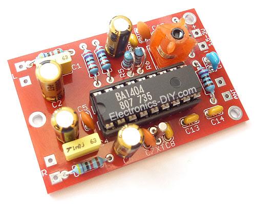
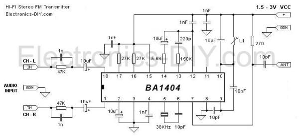
Another quality of the presented BA1404 transmitter is a crystal clear stereo sound and improved sound separation. There are several factors that account for improved sound quality and a separation. First reason is the use of 38 KHz crystal which provides rock solid frequency for stereo encoder. Another reason is the use of two 1nF decoupling capacitors one for BA1404 chip and another for 3.5 variable coil. These capacitors have to be as close as possible to a BA1404 chip and a variable coil because this will GREATLY improve the sound quality, sound separation and even frequency stability as well. What they do is filter out the noise in the incoming DC voltage. If the noise enters BA1404 chip stereo generator will include it in a transmitted sound affecting both the sound and multiplex signal that is responsible for generation of the clear stereo signal. If that noise enters it will also be included in a generation of subcarrier frequency affecting the frequency stability. Most people are not aware of how important this is and might place them in a wrong location, away from the target components which provides no use, or worse decide not to use these capacitors at all.Another factor that is extremely important and which improves overall quality of the whole BA1404 transmitter including frequency stability, sound quality and sound separation is the use of the ground plane on the transmitter’s PCB. It is recommended that ground plane should always be used in circuits that deal with higher frequencies.

BA1404 HI-FI Stereo FM Transmitter 88 - 108 MHzAntenna

For optimum transmission range the length of the antenna should be 1/4 or 1/2 of the wave length of the transmitted frequency. Use this simplified formula to determine the antenna length for 1/4 wave length antenna type:

(30000 / Transmitted Frequency) / 4 = Antenna Length (in cm)

Example:
(30000 / 88MHz) / 4 = 85cm Antenna
(30000 / 108MHz) / 4 = 70cm Antenna

About The Author

Ibrar Ayyub

I am an experienced technical writer holding a Master's degree in computer science from BZU Multan, Pakistan University. With a background spanning various industries, particularly in home automation and engineering, I have honed my skills in crafting clear and concise content. Proficient in leveraging infographics and diagrams, I strive to simplify complex concepts for readers. My strength lies in thorough research and presenting information in a structured and logical format.

Follow Us:
LinkedinTwitter