
Description
Recently I got a new motorbike and on my second trip out, with only 50 miles on the clock the rectifier/regulator unit failed. The battery on a bike is pretty small and with the head light permanently on and all the ECU, ignition and fuel injection stuff it didn’t take long to run the battery flat. Fortunately I’d stopped and there wasn’t enough charge left to turn the engine over, but it’s possible for the battery to discharge and the bike to cut-out while riding – not good.
After a bit of research it became apparent that this type of failure is common, with the regulator either not charging the bikes battery, or overcharging it. Despite the ECU monitoring the voltage it doesn’t generate any indication of a low voltage condition to alert the rider.
This project aims to provide the rider with an early warning of a fault to the bikes battery/charging system by connecting to the electrical supply on the bike and continually measuring the voltage. If it goes outside of programmed set points it alerts the rider by activating an LED.
The design can be applied to cars as well as motorbikes and could also be used for other voltage monitoring applications.
Component values shown on the schematic are for operation with a 12 volt automotive electrical system.
Circuit Description
Hardware
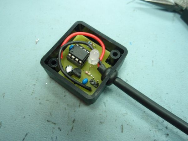
The circuit use a PIC12F683 microcontroller programmed with firmware (see download section) that measures the vehicle supply voltage using an Analogue to Digital Converter (ADC) and compares it to set voltage points, activating the bi-colour LED to alert the rider when the voltage goes outside the expected normal operating range.
The vehicle supply voltage feeds IC2, an LM2931AC-5.0, Low Drop Out (LDO) voltage regulator IC to power the microcontroller. This part is designed for use in automotive applications and can withstand load dumps and reverse transient. There are several variants of this part, so make sure to get the ‘AZ’ or ‘AC’ variant as these have a +/-3.8% or 2.5% tolerance output. Diode D1 protects the circuit from accidental reverse polarity of the input supply voltage. Capacitors C2 and C3 are required to stabilise the regulator as per the datasheet for the device. The design uses a 47µF capacitor for C3, but a 22µF part can also be used.
![]() The LM2931 was chosen because it is designed for use on automotive electrical systems where the electrical supply is quite hostile. For other applications the following devices could be used as an alternative to the LM2931.
The LM2931 was chosen because it is designed for use on automotive electrical systems where the electrical supply is quite hostile. For other applications the following devices could be used as an alternative to the LM2931.
An LM78L05 is cheap and easy to find, it’s not ideal but should work. If you do use it, you can omit C3, but will need to replace C2 with a 1µF / 25 volt electrolytic.
For a precision 5 volt LDO regulator look at the LP2950CZ-5.0, this will need a 1µF / 25 volt electrolytic capacitor for C2 and 1µF / 6.3 volt or 10 volt electrolytic for C3.
The status LED is a 5mm bi-colour common cathode part, We used an HLMP4000 part although any bi-colour LED should work here. It should have a milky white or defused body since it needs to ‘mix’ the red and green to get orange. Clear LEDs don’t do this so well.
The PIC12F683 contains a 10-bit internal Analogue to Digital Converter (ADC) that compares the voltage on the AN2 input (Pin 5) with a reference voltage. This design uses the Vdd 5 volt supply to the PIC as the reference voltage (Vref).
Since the range of voltages in a 12 volt automotive system can go up to about 15 volts, and higher if the alternator regulator fails the input voltage needs to be scaled down so it falls within the range 0 to 5 volts when presented to the PIC. This is done using a voltage divider comprising R1/R2 which are 1% precision resistors to help with accuracy. There is an optional capacitor C4 which can be used to filter the input, however this isn’t used here.
Should the supply voltage exceed 20.16 volts the output from voltage divider R1/R2 will exceed 5 volts. The PIC has internal clamp diodes on the inputs connected to Vdd and Vss, the excess voltage will be clamped by the diode while resistor R1 limits current to just a few milliamps.
For more detail: Automotive Voltage Monitor using PIC12F683
About The Author
Ibrar Ayyub
I am an experienced technical writer holding a Master's degree in computer science from BZU Multan, Pakistan University. With a background spanning various industries, particularly in home automation and engineering, I have honed my skills in crafting clear and concise content. Proficient in leveraging infographics and diagrams, I strive to simplify complex concepts for readers. My strength lies in thorough research and presenting information in a structured and logical format.
Follow Us:LinkedinTwitter