Here I give you my project on Automated Railway Gate Controlled by PIC16F877A . It is very good project and if it is implemented by railway then they can save lots of money to paying salary for this purpose. For that project I use PIC16F877A, LCD display, two pressure Sensor (situated in rail line) ,Traffic light and motor (For closing and opening the railway gate).
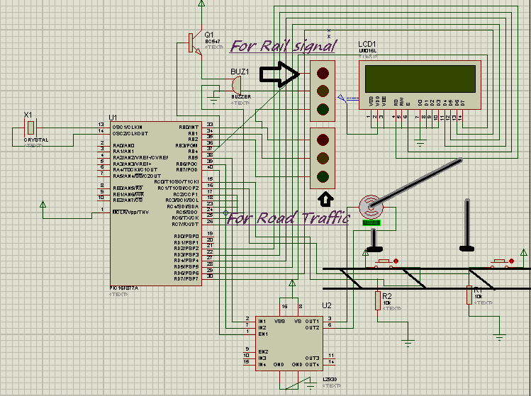
Project Detail: Here I use two pressure sensor places in rail line 1 km way from both side of rail gate. When Rail is coming and touch the first pressure sensor the motor is start rotating and the gate is attach with motor and it slowly down and close the door. Before close the door rail traffic light was red and for road traffic it was green. After closed the gate rail signal is green and road traffic is red. Now train cross the gate after crossing gate it will touch other pressure sensor which is situated 1 Km way from other side of crossing. Now motor start anticlockwise rotating and gate slowly opening and after complete opening of the gate road traffic light will green and railway signal will red. I used LCD to display the total status of railway gate control.
I use Proteus to simulate my project and Micro c pro for writing the embedded C . In bellow found the embedded code which I used.
For more detail: Automated Railway Gate Controlled by PIC16F877A
About The Author
Ibrar Ayyub
I am an experienced technical writer holding a Master's degree in computer science from BZU Multan, Pakistan University. With a background spanning various industries, particularly in home automation and engineering, I have honed my skills in crafting clear and concise content. Proficient in leveraging infographics and diagrams, I strive to simplify complex concepts for readers. My strength lies in thorough research and presenting information in a structured and logical format.
Follow Us:LinkedinTwitter