Over the last year I’ve been working towards an underwater sonar system for ROVs and surface boats. In order to learn the basic signal processing required to detect the echoes, I initially got a simple sonar working in air with a desktop conferencing USB speaker/mic running on Windows. A writeup, including source, is here. That article describes the algorithms used in detail and would be a good read if you want the details of how this works.
The next logical step seemed to be to get it working on a microcontroller. There are plenty of low cost ultrasonic sonar modules available that work really well in air, but the idea was to work towards getting a sonar that worked in water. There are currently no low cost sonar modules for hobby use in water. Additionally, the low cost modules only give one echo – with a signal processing approach like this, you get a series of echoes that may convey more information about the environment. As an example, a boat floating above a school of fish could detect both the fish and the bottom.
I selected a Stellaris Launchpad because of the high speed analog to digital converters (ADC) and the 32 Kof RAM. At the required sample rates, the Launchpad has just enough RAM to send a chirp, and then record a fraction of a second of audio so that the echoes can be determined. Higher frequency sound will require a higher sampling rate, so I may need to switch to a Teensy 3.1, which has 64K of RAM.
A chirp waveform is computed and sent to a small piezo speaker driven by a simple transistor circuit. The piezo supply voltage (VCC in the diagram below) is provided by 3 nine-volt batteries in series to obtain 27V. This diagram shows how it is connected. This is not my diagram – I found it online, but I don’t have a reference. If this is yours, please drop me a line.
The return echo is detected by a small amplified microphone from Adafruit. I like this module because it has an integrated level shift. Rather that swinging from -V to +V, it is shifted to 0 to +3.3V so that it can be connected to an ADC. It’s very convenient.
A couple 3D printed parts hold it all to the board just to keep it pointed in the right direction
The chirp is sent, and the audio immediately starts recording to catch the echo. The same correlation function as used in the previous article is used to pull the echoes out of the recorded audio. The intensities of the correlation function are sent through the debug port to the PC so that it can be plotted.
I need to work on optimizing the echo detection code – currently it works on the audio from each pulse for 4 seconds or so. Also, the power output of the audio transducer is very low, so range is pretty limited. It has an effective range of between 3-9 feet. Closer than 3 feet, the echo is hard to pick out of the noise produced when the pulse is sent.
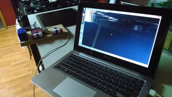
As in the original experiments with the speaker/mic, the results are plotted with a simple Python program set up similarly to a fishfinder display. The results of a test run are shown below. Source for the Python display is modified from code from the previous article.
I am an experienced technical writer holding a Master's degree in computer science from BZU Multan, Pakistan University. With a background spanning various industries, particularly in home automation and engineering, I have honed my skills in crafting clear and concise content. Proficient in leveraging infographics and diagrams, I strive to simplify complex concepts for readers. My strength lies in thorough research and presenting information in a structured and logical format.
This website uses cookies to improve your experience. We'll assume you're ok with this, but you can opt-out if you wish. ACCEPTCheck Privacy Policy
Manage consent
Privacy Overview
This website uses cookies to improve your experience while you navigate through the website. Out of these, the cookies that are categorized as necessary are stored on your browser as they are essential for the working of basic functionalities of the website. We also use third-party cookies that help us analyze and understand how you use this website. These cookies will be stored in your browser only with your consent. You also have the option to opt-out of these cookies. But opting out of some of these cookies may affect your browsing experience.
Necessary cookies are absolutely essential for the website to function properly. This category only includes cookies that ensures basic functionalities and security features of the website. These cookies do not store any personal information.
Any cookies that may not be particularly necessary for the website to function and is used specifically to collect user personal data via analytics, ads, other embedded contents are termed as non-necessary cookies. It is mandatory to procure user consent prior to running these cookies on your website.