
Making A Real Time Clock (RTC) is simple if you use a helper chip such as a DS1307 because you do not need to keep track of the length of each month or account for leap years. It is all done for you, plus you get the benefit of a battery back up system that means it won’t lose the data or time when you turn off main power.
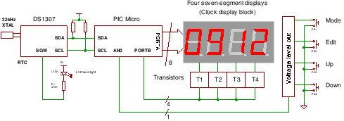
This PIC project uses an I2C (or IIC) Real Time Clock IC (DS1307) and a four digit seven segment display to create a standard desk clock.
Note: If you typed DS1703 Real Time Clock to find this page you probably mis-spelled the chip type.
Anyway you can find a DS1307 (RTC) Real Time Clock IC project and information on this page.
Note: This RTC project has been updated with easier to use software i.e. the software loaded into the PIC (Note the compiler is free for <2k and currently the code uses about 1550 bytes). There are also two additional modes one for information and one for debugging: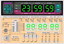
The first new mode is found when pressing key 3 which will display an indication of what the current display is showing (sometimes it is hard to figure that out by just looking at numbers!). The second is when pressing key 4 which will cycle through all the RA0-RA7 output pins and show the LEDs lit on the 7-segment display. This means it is easier to figure out if the RA0-RA7 connections are correct when you wire it up (Note RA5 is not used as it can only be an input – see detail below). The project has also been updated to use the latest MikroC compiler 6.0.1
Specification
| Accuracy | Watch crystal spec typically 20ppm |
| Compiler | Mikroelectronika MikroC Compiler Free! |
| Target | 16F88 (re-targettable to other PICs that have Analogue input AN0). |
| Software level | Medium. |
| Software notes | Switching between i/p & o/p to read analogue/drive display. Using I2C routines. |
| Hardware level | Easy. |
| Hardware notes | Special care must be taken in placing the DS1307 and the crystal. |
| Project version | 1.02 |
Real Time Clock IC : DS1307
Although the PIC16F88 has a built in oscillator for a 32kHz watch crystal a DS1307 is easier to use on a bread board. This is because you can control the layout of the circuit more easily.
The RTC also makes the software easier as it takes care of all calendar functions; accounting for leap years etc.
The DS1307 (RTC) Real Time Clock IC (an I2C RTC) is an 8 pin device using an I2C interface (although the data sheet does not mention I2C to avoid royalty payments!). It has 8 read/write registers that store the following information:
| Address | Register function |
| 0 | Seconds 0-59 |
| 1 | Minutes 0-59 |
| 2 | Hours 0-24,1-12 |
| 3 | Day 1-7 |
| 4 | Date 1-31 |
| 5 | Month 1-12 |
| 6 | Year 0-99 |
| 7 | Control |
Note: Addresses 0x08 to 0xf3 are user RAM and if you use a backup battery these are then non volatile ram i.e. they will save their contents after the power is off – so you have an extra 56 bytes of ram to play with! less the one used for storing the year high digits at 0x20– you could change this to not use the RAM but it is also used as an initialisation check – see the code.
Note: Address 3f is used in this project as a check to see if the clock needs initialising and to store the upper year digit (for easier coding).
The last address 0x08 is the CONTROL address and it determines what is generated at the SQW/OUT pin. You can control the level directly via I2C or set it to 1Hz, 4096Hz, 8192Hz, or 32768kHz. In this software it is set to 1Hz and used to drive an LED that can be used as a back light for the 4×7-segment module (if you shine a light through the module you’ll see the two central holes (like a colon character) that are between the left and right sets of two 7-segments. This is usually used to flash seconds so placing the LED behind this will achieve that operation.
In the same way as the I2C pins you need to add a pull-up to V+ at the SQW/OUT pin to see any output signal as it is an open drain output! or as in this circuit, an LED and 470R resistor are connected in series and to the +5V power. The other end goes to the SWQ/OUT pin of the DS1307.
Real Time Clock IC : Embedded control bits
There are two specific ‘gotcha’ type controls embedded in the addresses which make using the chip slightly more complicated.
Real Time Clock IC DS1307 : Clock halt / Minutes and Seconds register
The most important is the Clock Halt Bit (CH) which is bit 7 of address 0. This is the register that controls ‘seconds’ and the CH bit has to be preserved otherwise the chip stops the clock. Writing zero to this bit resets the CH bit so that the clock runs.
Note: You have to reset the CH bit to zero to let the chip operate!
Warning: The default state of the DS1307 is undefined
so you must clear the CH bit to start the oscillator.
In general you should leave this bit at zero and only set it if you have to. This bit is contained within register zero which is also the “minutes” and “seconds” register. In general keep this bit at zero unless you are updating the seconds part of the register (you don’t want the seconds changing while you are editing them).
Real Time Clock IC DS1307 : 24/12 Hour control
The second is the 24/12 hour control which is bit 6 of address 2. It is set high for 12 hour mode and low for 24 hour mode. In this project it is set low for 24 hour mode.
The problem with these two bits is that you have to preserve them when accessing the registers to write data and ignore them when reading out values for display. Its not a big problem and you can see how it’s done when you look at the code (see function edit_DS1307() and the 1st 2 case statements for address 0 (CH) and 2 (12H/24H) ).
Real Time Clock IC : 32kHz oscillator
Surprisingly making an accurate 32kHz oscillator is a difficult task (much more than a high speed oscillator e.g. a MHz crystal oscillator). This is because low speed oscillator drivers are designed for low power operation. That means high impedance and therefore low current which makes the driver extremely sensitive to noise (or any nearby signals which can capacitively couple to the crystal wire).
Using the DS1307 lets you put the crystal in the least noisy part of the board. In addition it sets the crystal load capacitance which is critical in making the crystal oscillate at exactly 32kHz – controlling its initial error i.e. for the specified ppm error value the load capacitance must be exact.
Note: A common way of calibrating a crystal (not in this project) is crystal pulling or changing the capacitance at one crystal pin relative to the other – so load capacitance is crucial.
The DS1307 loads the crystal with 12.7pF so you need to buy a crystal that is defined to use this load capacitance. Circuit layout also affects the capacitance at the crystal pins so you must keep the crystal as close as possible to the chip and the tracks from crystal to chip must be short.
To ensure the crystal oscillates correctly you must ensure that :
- Crystal uses 12.7pf load capacitance (correct crystal type).
- The crystal is close to the IC.
- The tracks are short.
- The chip supply has lots of decoupling (capacitors from +5V to GND). e.g. A 100n and a 10n
- There are no signal tracks near to the crystal.
- For a pcb: It has a guard ring and a ground plane and away from digital signals.
If you are doing a board layout there is good advice in the PIC 16F88 datasheet (Timer 1 section) on crystal pcb guard rings. Dallas recommends Application note 58 which I have not read yet.
Real Time Clock IC : Power failure.
The DS1307 detects a power failure if its input voltage (Vcc) falls below (VBat) and automatically switches to the Vbat supply input (you should use a lithium 3V battery here as the backup battery). It also inhibits I2C control signals until Vcc is 1.25 x Vbat so you won’t be able to put bad data into the chip as the power is failing!
Input keys
To save microcontroller pins there are four input keys which are all connected to a single analogue input pin. This pin also drives one of the seven segment display LEDs so it has to be switched between input (to read the analogue voltage) and output (to drive the led).
Note: This works because the analogue input is switched to receive analogue for only (150us approx) there is a 100us delay to let the inputs settle (just a guess and could be made lower – but it is not critical in this application). Then the input signal is read. Because of persistence of vision (on which the entire display methodology depends) your eye can not see this missing light pulse so it looks like the display is completely steady!
Each key pulls the analogue input to a different voltage level which you can easily read using the ADC (RA0).
7 Segment Display
The display is made up of four 7 segments built into a convenient block where all 8 led drive lines are connected together. You could wire up individual 7-segments to achieve the same result but doing it on a soldered breadboard is a pain. The block just saves you effort (and errors in wiring). So this results in 8 data lines and 4 digit select lines.
Initially I used RA0 to RA7 as the data line drivers and RB2,5,6,7. Then I realised that RA5 is only allowed to be an input because it is also multiplexed with the reset pin MCLR. Since it had been wired up this way the simplest solution was to eliminate RA5 but how do you do that without changing all the drive data definitions?
When eliminating RA5 I moved RA6 and RA7 down to bits b5 and b6 so this leaves the LED drive for the decimal point unconnected but that is OK since we are not using that part of the 7-segment display.
So the solution is to use a helper function that maps the bits 6,7 to bits 5,6 just before outputting the data to the 7-segment LED bus and the function has an obvious name:
move_b6_b7_to_b5_b6(Byte num)
Digit Select lines
The digit select lines are each driven by a transistor switch that allows more current if needed ( note I have not measured the exact current drawn as it depends on the refresh rate of the display).
Display Refresh and current limit resistors
Yes there are none! i.e. between the RA bus and the LED drives there are no limit resistors.
Why?
In all other circuits you can see them. I chose not to use them since the display is only ever driven in refresh mode. If it were driven directly then the LEDs would blow up.
If you are uncomfortable with this then add 8 off of 330R or 470R resistors to limit the maximum current to each LED (e.g. if the are driven permanently during testing) from each drive RA bus to the 4×7-segment display.
The reason that it works is to do with heat generated – as the current flows in the LED the junction heats up and if you drive too much current then it melts the internal wires – which is where the max. current limit comes from.
When driving the display in refresh mode the display is held on for a very short time compared to the time it is held off and this defines an average current that is within the current limit of each LED.
Hey.. don’t knock it… it works fine…promise.
Note: The idea comes from chip design where the current drawn by the device depends on the switching speed of the system since for FETs maximum current is drawn when both upper and lower FETs in a switch are on i.e. during the transition from current level to next i.e. when switching.
Using the Real time Clock IC project
When the system powers up the ram location 0x3f is checked for value 0x20. If this exists then it means that the backup battery has saved contents of the RAM and all the registers have therefore been initialised. So the software skips the initialisation sequence.
For more detail: A Real Time Clock IC (DS1307) project using the PIC micro.
About The Author
Ibrar Ayyub
I am an experienced technical writer holding a Master's degree in computer science from BZU Multan, Pakistan University. With a background spanning various industries, particularly in home automation and engineering, I have honed my skills in crafting clear and concise content. Proficient in leveraging infographics and diagrams, I strive to simplify complex concepts for readers. My strength lies in thorough research and presenting information in a structured and logical format.
Follow Us:LinkedinTwitter