
-
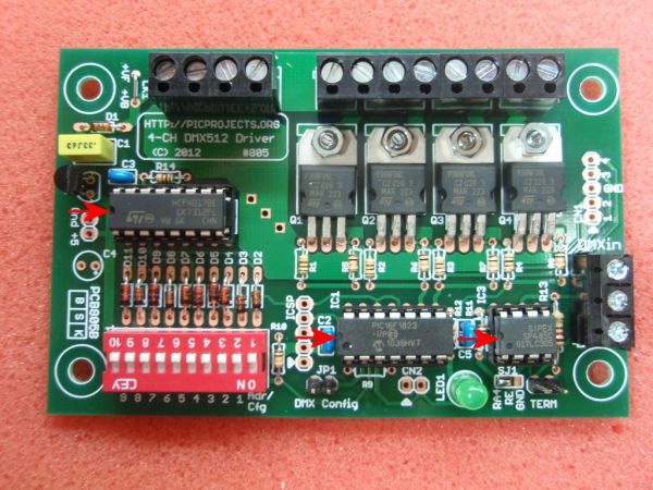
The original DMX512 driver project #800 is now redesigned to incorporate the optional address configuration switch on the main PCB.
-
The no-switches in-band DMX configuration feature is still retained
-
Double sided PCB has resulted in a more compact board size.
-
Firmware has been updated to run a latest generation enhanced midrange PIC16F1823 processor.
Description
This project is a 4 channel DMX512 driver board. It features four power MOSFETs that can be configured to operate in PWM mode or as on/off outputs. The driver can be configured to use any four consecutive addresses across the full 512 channel address range. It can drive LED arrays or low voltage lamps with either an 8 bit (256 step) PWM dimming signal or digital on/off mode under DMX control.
Feature list:
- 4 channels with low side, open-drain ‘N’-channel MOSFETs providing up to 3 amps per channel
- Channel output current switching from 1mA to 3 amps
- Channel voltage range from 3 to 36 volts
Outputs can drive LED modules, strips, lights or low voltage lamps up to 35 watts.
- Two output modes:
- 8 bit resolution PWM mode with a PWM period of 5ms (200Hz).
- digital on/off output.
- Operating mode is individually configurable for each output
- Operate as four independent outputs or Ganged operation where all four outputs are controlled from the base address DMX data channel
- When no DMX data is received the driver can be configured to turn off all outputs, or leave them in their current state.
- Configuration held in EEPROM so once configured can operate with no external switches or jumpers.
In keeping with the original 4-channel DMX driver project #800, the firmware supports a minimal external hardware design.
Although the new PCB805B has a configuration DIP switch on the board, the DMX base address and configuration modes are stored in the microcontrollers internal non-volatile EEPROM. Once settings have been made the firmware uses the saved settings from the EEPROM if no DIP switch is detected.
Additionally the original configuration via in-band DMX channel data is still supported. Fitting a single jumper puts the firmware into ‘in-band’ configuration mode. DMX data sent in the first four channels is saved to the EEPROM allowing the DMX base address and configuration word to be setup without the use of the external DIP switch.
The project page for the previous version of the 4-Channel DMX driver can be found here:
Previous 4-Channel DMX driver
The following options for the DMX512 PWM Driver are available to buy from the Picprojects eShop
- Complete kit of parts, including PCB and pre-programmed PIC microcontroller, order code #805K
- PCB805 only, order code #805P
- PIC microcontroller pre-programmed with DMX firmware, order code #PRG805
Buy a complete kit of parts from the PICPROJECTS online eShop.
Kit contains all the components required to assemble the complete 4-Channel DMX512 Driver project, including the PCB and microcontroller pre-programmed with the DMX805 firmware.
Order code 805K
| Component | Description |
| R1,R2,R3,R4 | 120R 0.125 watt |
| R5,R6,R7,R8,R10,R11 | 10K 0.125 watt |
| R12 | 330R 0.125 watt |
| R13 | 120R ( 0.25w or 0.5 watt) |
| R14 | 1K0 0.125 watt |
| R9 | not used |
| All resistors are 5% carbon film. Where 0.125 (1/8) watt parts are specified these are required to fit on the PCB due to size constraints. |
|
| C1 | 330nF polyester (5mm pitch) |
| C2,C3,C5 | 100nF multilayer ceramic (2.5mm pitch) |
| C4 | not used |
| D1-D11 | 1N4148 diode |
| IC1 | PIC16F1823-I/P (Must be programmed with DMX firmware) |
| IC2 | 78L05 voltage regulator |
| IC3 | MAX481 (or equivalent RS485 transceiver) |
| IC4 | HCF4017B |
| Q1,Q2,Q3,Q4 | STP36NF06L logic level N-MOSFET (STP20NF06L alternate part) |
| LED1 | 5mm LED green |
| SW1 | 10-way DIP switch |
| CN1 | 5-pin 0.1″ header (not used) |
| ICSP | 5-pin 0.1″ header (not used) |
| CN2 | 2-pin 0.1″ header (not used) |
| JP1 | 2-pin 0.1″ header |
| TERM | 2-pin 0.1″ header |
| 2,54mm jumper links for shorting JP1 / TERM header | |
| DMXin | 3-way, 5mm, screw-terminal |
| Power-in terminal block | 4-way, 5mm, screw-terminal, 16 amp (2 x 2-way end stackable) |
| Channel output terminal block | 8-way, 5mm, screw-terminal, 16 amp (4 x 2-way end stackable) |
| IC1 socket | 14-pin DIP socket |
| IC3 socket | 8-pin DIP socket |
| IC4 socket | 16-pin DIP socket |
| Miscellaneous item x 4 | M3 nut + M3 x 6mm machine screw (to mount MOSFET to PCB) |
Notes:
-
- Apart from resistor R13 all other resistors are 0.125 (1/8) watt parts. These a specified for physical space constraint reasons on the PCB.
- Apart from resistor R13 all other resistors are 0.125 (1/8) watt parts. These a specified for physical space constraint reasons on the PCB.
- The output driver MOSFETs Q1-Q4 are STP36NF06L or STP20NF06L. These are logic level devices designed to operate with a low gate drive voltage. If an alternative non-logic level part is substituted you may need to derate the maximum output current per channel
- Alternative pin-compatible parts exist for the RS-485 transceiver, IC3.
- SP485 (EXAR)
- ST485 (ST)
- MAX483 (Maxim)
- MAX485 (Maxim)
- other parts are also available
- The PIC16F1823-I/P (IC1) requires programming with the DMX firmware. This part is only available from Picprojects as a pre-programmed and code protected part. (the firmware is not available to download)
See Pre-Programmed PICs section of the on-line eShop
Construction notes:
- Please read through this section at least once before starting assembly of the PCB
- Assembly is straightforward. You will need previous experience soldering electronic components, a suitable soldering iron, hand tools and a multi-meter.
- All photographs in the section link to a hi-res 1024×768 image for more detail.
- Refer to the schematic diagram and component listing above for component values used in this project
For more detail: 4 Channel DMX512 Driver for PIC16F1823
About The Author
Ibrar Ayyub
I am an experienced technical writer holding a Master's degree in computer science from BZU Multan, Pakistan University. With a background spanning various industries, particularly in home automation and engineering, I have honed my skills in crafting clear and concise content. Proficient in leveraging infographics and diagrams, I strive to simplify complex concepts for readers. My strength lies in thorough research and presenting information in a structured and logical format.
Follow Us:LinkedinTwitter