
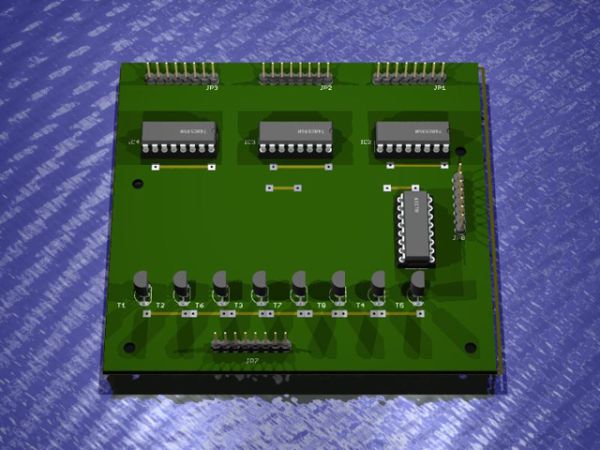
This is a 24×6 LED matrix control board based on Syst3mX schematics on Instructables. The board is connected on the LED matrix board and an external MCU or Arduino is required to produce the control signals that are feed on GP8.
The circuit is able to drive a 24×6 LED matrix using an external MCU or Arduino board. The LED matrix columns are connected on JP1, JP2, JP3 and the 6 rows are connected on JP7. There is also the option to connect 2 more rows (total 8 rows) to make a 24×8 LED matrix.
The control is done externally applying the signals on JP8 as is shown on the diagramm below:
– GND is the signal ground
– VCC is 5V in reference to GND
– RCK is SC signal of SPI (latch)
– SCK is CLOCK signal of SPI
– SER is DATA dignal of SPI
– CLK is CLOCK signal of 4017
– RES is RESET signal of 4017
Control signals can be easily generated by an Arduino UNO or Duemilanove using some code . You may refer to:
– http://arduino.cc/en/Reference – general Arduino reference
– http://arduino.cc/en/Reference/SPI – SPI Protocol reference
– Sample Code can be found here
– You can make your own symbols using this EXCEL sheet
– Check how 4017 IC is working: http://www.doctronics.co.uk/4017.htm
For more detail: 24×6 LED Matrix Control Circuit
About The Author
Ibrar Ayyub
I am an experienced technical writer holding a Master's degree in computer science from BZU Multan, Pakistan University. With a background spanning various industries, particularly in home automation and engineering, I have honed my skills in crafting clear and concise content. Proficient in leveraging infographics and diagrams, I strive to simplify complex concepts for readers. My strength lies in thorough research and presenting information in a structured and logical format.
Follow Us:LinkedinTwitter