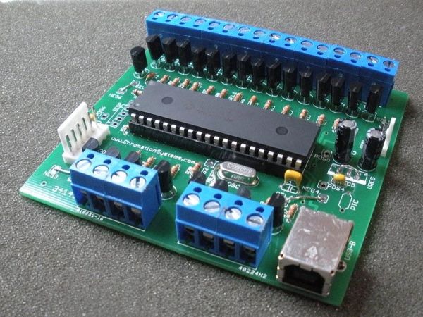
24 Channel USB Connected LED Controller, upto 1A per Channel
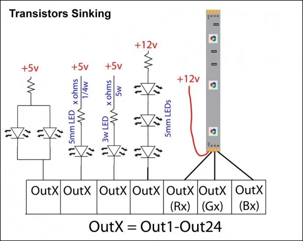
This device is designed to be a versatile high-current LED controller, with the ability to sink or/and source currents up to 1A per channel with dissipation of up to 2.5w per channel. The various jumpers and transistor placement allow the device to control many different types of LED configurations with LED voltages of up to 36v.
Easily controls 5mm , 1w, 3w, 3w RGB, 5w RGB, 12v RGB LED lightstrip, 12v solid color light strip, common anode RGB LEDs, common cathode RGB LEDs. Any combination of LEDs in parallel/series. Whatever kind/wattage/configuration can be made to work, to a max of 1A per channel or 2.5w dissipation.
A PIC18F4550 controls 24 high-current darlington transistors. The PIC is ready for USB communication and using Microchip’s Library there is a multitude of USB connected devices can be made. From a simple emulated serial port, keyboard, mouse, HID, MIDI Devices, Audio Devices, and more. The available premium firmware allows the device to interact with the ColorMotion computer software, to create and upload patterns and settings to the device.
There are 4 pins left to use for other purposes, such as AdC, more transistors/mosfets, shift register whatever is needed. Accessed via the 6-pin polarized header, which can be used to connect to RA0, RA1, RA2, RA3, V+ and V-.ase. It accepts data from a PC/MAC/Linux over emulated serial port to the circuit board which outputs 8-bit PWM for all 24 outputs.
There are kits available in the Chromation Systems Store and all the files to recreate this project is in the ZIP file below.
Previous Version Assembly Instructions, Datasheet, Updates and More Info Can Be on the Main Website
The zip includes PCB diagram, Schematic Layout, and drill files. It is a single sided version of this circuit, so it is very DIY PCB friendly.
The 48 Channel Mono / 16 Channel RGB LED Controller, which is also USB connected, and is made for lower current LEDs is now available.
Supplies
Electronics: Purchase a Kit from The Store or Purchase a PIC or PCB separate.
- 18F4550, DIP Buy One
- Circuit Board, v.3 Buy One
- 24x MPSW45AG Darlington Transistors or similar
- USB Type-B jack, board mount
- 20 mhz, version 3 can use any type, v1 & v2 require a series oscillator
- 10kohm 1/4w resistor
- 24x 1k ohm 1/6w resistor, value may vary depending on transistor
- 220nF disc capacitor, VUSB
- 2x 0.1uf disc capacitor
- 2x 1uF electrolytic capacitor
- 2x 22 pF disc capacitor
- 5 pin ICSP header, optional
- 6x 4-position screw down terminal blocks
- 2-pin header, KK6410, use is optional
- 2-pin housing, KK6471, use is optional
- 6-pin header, KK6410, use is optional
- 6-pin housing, KK6471, use is optional
- 8 wire crimps for housings
- 7805, 5v regulator, optional, can’t be used in most cases
- Button assembly parts: Momentary Push button, perfboard, ribbon cable, and 10kohm resistor
Tools:
- Soldering Iron
- Diagonal Cutters
- Wire Strippers
- Flat screw driver for terminals
- Multi meter
Other: Not included with the kit
- USB Type A to Type B cable
- LEDs or LED Strip, Find Some In The Store
- Resistors for the LEDs
For controlling lower current LEDs over USB, please view 48 Channel Mono / 16 Channel RGB LED Controller
Resistors
Resistors:
- Start with the transistor base resistors, R1-R4 are all 1k ohm(Brown – Black – Red)
- R25 is a 10k ohm (Brown – Black – Orange) pull-up for MCLR
- R26 and R27 are 22 ohm (Red – Red – Black) for the USB Data lines, these must be crossed on version 3 PCBs, one on the top side, and one on the bottom side of the PCB. See Images.
Select Jumpers
This board features jumpers to select if the transistors will be sinking or sourcing current. The board’s transistors are laid out with 16 on one side and 8 on the other. Each side can be set to sink or source voltage based on the SEL jumpers and the position of the transistors. SELx to NEGx for sink, SELx to POSx for source.
Set all transistors to sink:
- SEL1 to NEG1
- SEL2 to NEG2
- SEL3 to NEG3
- SEL4 to NEG4
- SEL5 to NEG5
- SEL6 to NEG6
Set all transistors source:
- SEL1 to POS1
- SEL2 to POS2
- SEL3 to POS3
- SEL4 to POS4
- SEL5 to POS5
- SEL6 to POS6
Set 16(Output1-16) to Sink and 8(Output 17-24) to Source
- SEL1 to NEG1
- SEL2 to POS2
- SEL3 to POS3
- SEL4 to POS4
- SEL5 to NEG5
- SEL6 to NEG6
See datasheet for more jumper selections.
*Note that each side has 3 selection points, so if it was needed, the main trace could be cut at any point and transistors on the same side could be mixed sink/source.
Oscillator, Disc Capacitors
Oscillator:
- Oscillator, OSC position, goes in either way
- C1 – 220nF, labeled 224M, goes in either way
- C2 & C3 are installed later, leave them out for now.
- C4 & C5 – 0.1uF, labeled 104, go in either way
- C6 & C7 – 22 pF, labeled 224, goes in either way
Socket:
- Line the notch on the end of the socket up with the notch in the top-side drawing.
- Carefully line up the pins with the holes on one row of the socket then hinge it down into the adjacent row of holes.
- Check to make sure all the pins are lined up, then press it in firmly.
For more detail: 24 Channel USB Connected LED Controller, upto 1A per Channel using PIC18F4550


 ChromationSystems-24ChanUSB_v1-1-eagle.zip